About this project
I’ve always loved remote-controlled things — they’ve always intrigued me, especially how they work internally. I
still remember my first RC car when I was 12: a small Monster Truck operating at 27 MHz that I absolutely loved…
until I took
it apart to see how it worked and accidentally broke it 🤦.
Fast forward 20 years (one 👷🏼♂️
engineering diploma and 👦🏻👶🏻 a couple of kids later), I wanted to share my passion for electronics and
computers with my children. Since I recently got a 3D printer, I decided to start a small DIY 3D-printed RC car
project with my 6-year-old. It’s not really about building the car itself — it’s about nurturing his curiosity
and exploring how things work, together.
Project current Status
| Step | Date |
|---|---|
| 01 - Establish the specs of the MET (Minimal Enjoyable Toy) | 09-2025 |
| 02 - Shopping list ! | 09-2025 |
| 03 - Start Modeling using fusion 360 | 11-2025 |
| 04 - Gear Modeling by a N00b | 11-2025 |
| 05 - Test fit read drive (and found my first issue) | 11-2025 |
| 06 - Hitting the breaks: Lessons in Torque | 04-2026 |
01 - Minimal Enjoyable Toy
To get a basic, functional RC car, we’ll need just a few core components:
- A structure
- Power
- Wheels
- 2 motors (one for drive, one for steering)
- A brain to control the car
- A receiver
- A transmitter for the Remote
In detail
Starting a project like this completely from scratch would be tough — especially when trying to keep a 6-year-old
interested 😄. So, I looked around for similar projects to use as a foundation. Call it cheating if you want,
but let’s not reinvent the wheel 😉.
After a few hours of YouTube research, I found a video that
matched exactly what I had in mind.
https://www.youtube.com/watch?v=AEbeUMzCr-k That gave us a great starting point to
refine our own version. Let’s
go through the main parts:
- 🛠️ Car body
-
The chassis will be designed in Fusion 360 and printed using my Bambu Lab A1 Mini — a small but surprisingly capable printer.
- 🪫 Power
-
A set of Li-ion batteries should provide enough juice to keep the car running for a while. Combined with a Battery Management System (BMS) and a step-up converter, it should form a reliable power source for this small RC build.
- 🛞 Wheels
-
I’m no expert in RC wheels, but 65mm seems to be a standard size for similar builds — so I’ll go with that for now.
- ⚙️ Motors
-
The plan is to use a brushless motor for thrust and an MG90S servo motor for steering — a simple and well-tested combo.
- 🧠 Brain + receiver
-
For the controller, I’ll be using an ESP32 Wi-Fi board. It can be powered by Li-ion batteries and offers built-in Wi-Fi, making it perfect for both control and future expandability.
- 📡 Transmitter
-
Any Wi-Fi-capable device can theoretically act as the remote. The initial idea is to send UDP packets from a phone or laptop to control the car.
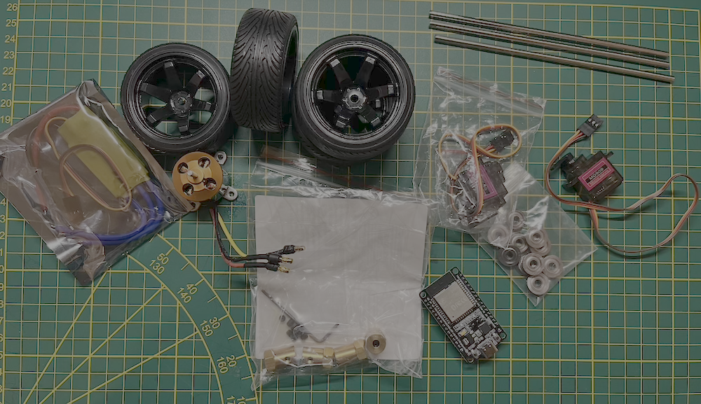
02 - Shopping list !
Here's the basic shopping list I purchased. Its not a complete one as I had other things laying around
| Image | Type | Model | Link | Price |
|---|---|---|---|---|
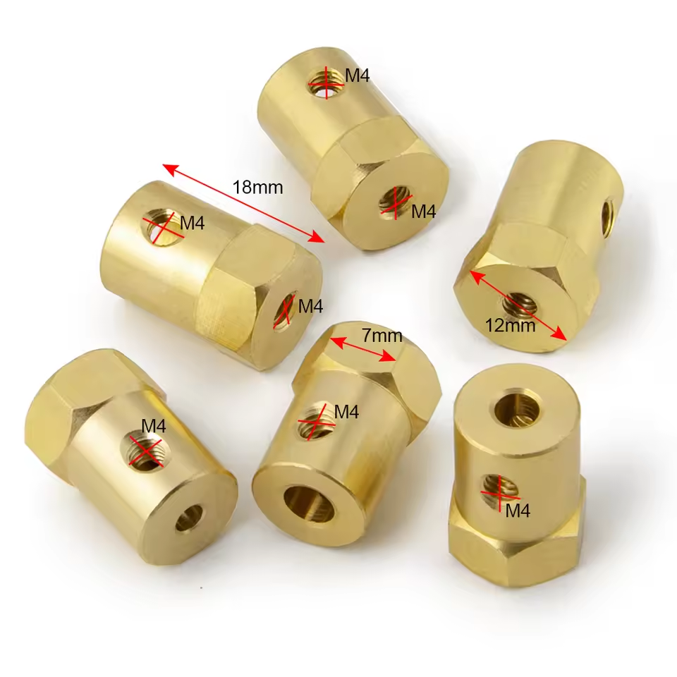 |
12mm Wheel Hex Coupler | Short Style-4mm | https://fr.aliexpress.com/item/1005006042552610.html | 3,39€ |
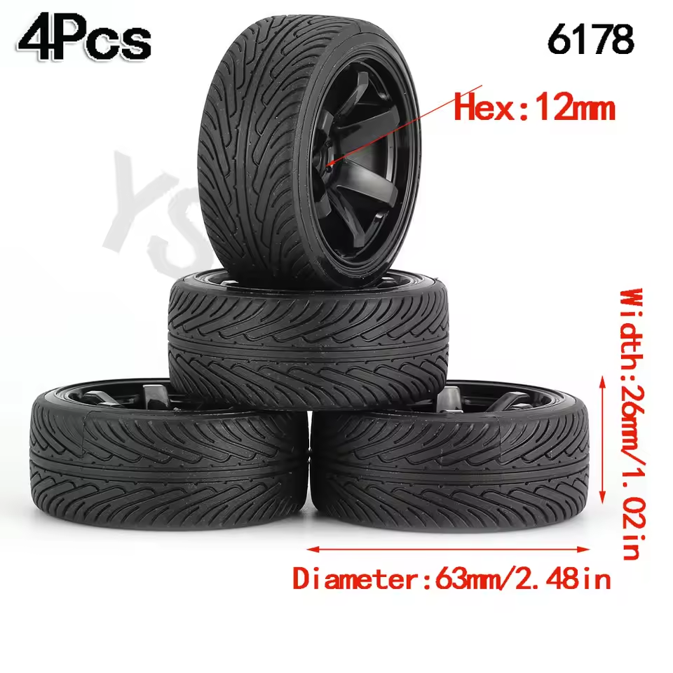 |
4 Rim Tyre 12mm hex | 6178 black (Not for drift) | https://fr.aliexpress.com/item/1005007129333294.html | 8,08€ |
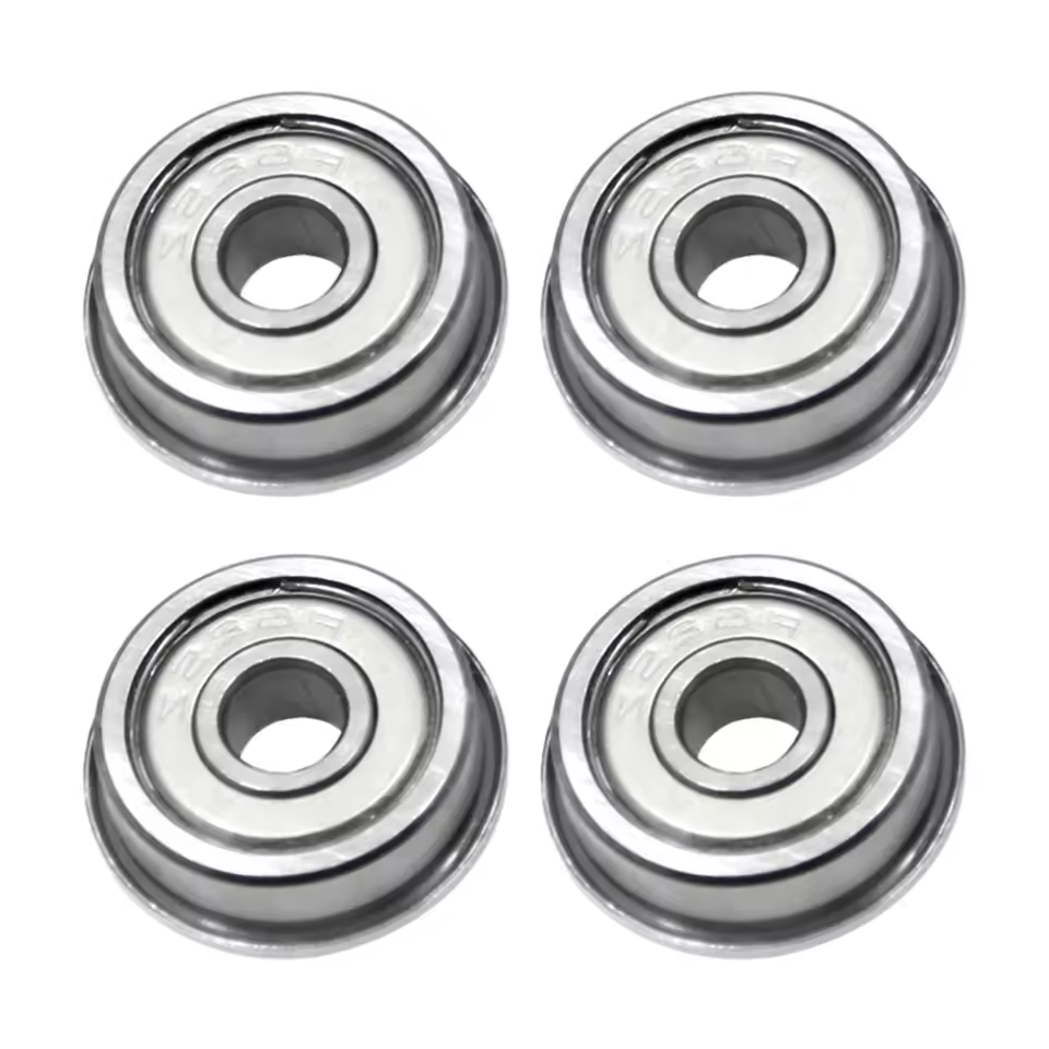 |
Flange Ball Bearings | F604ZZ | https://fr.aliexpress.com/item/1005001473790914.html | 4,79€ |
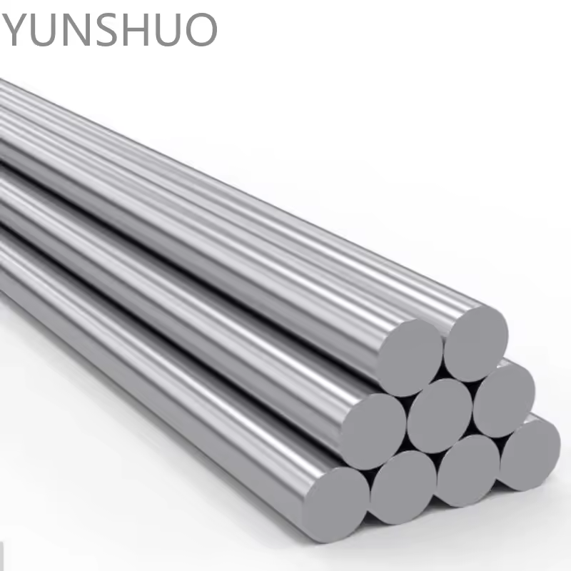 |
Rear axel shaft | 150mm x 4mm | https://fr.aliexpress.com/item/1005006293171727.html | 0,97€ |
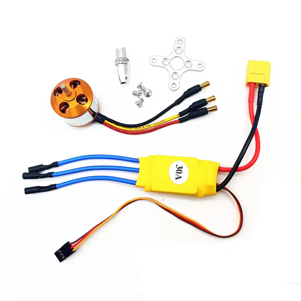 |
Brushless Motor with 30A Brushless ESC | KV2200 30A | https://fr.aliexpress.com/item/1005008190900818.html | 9,49€ |
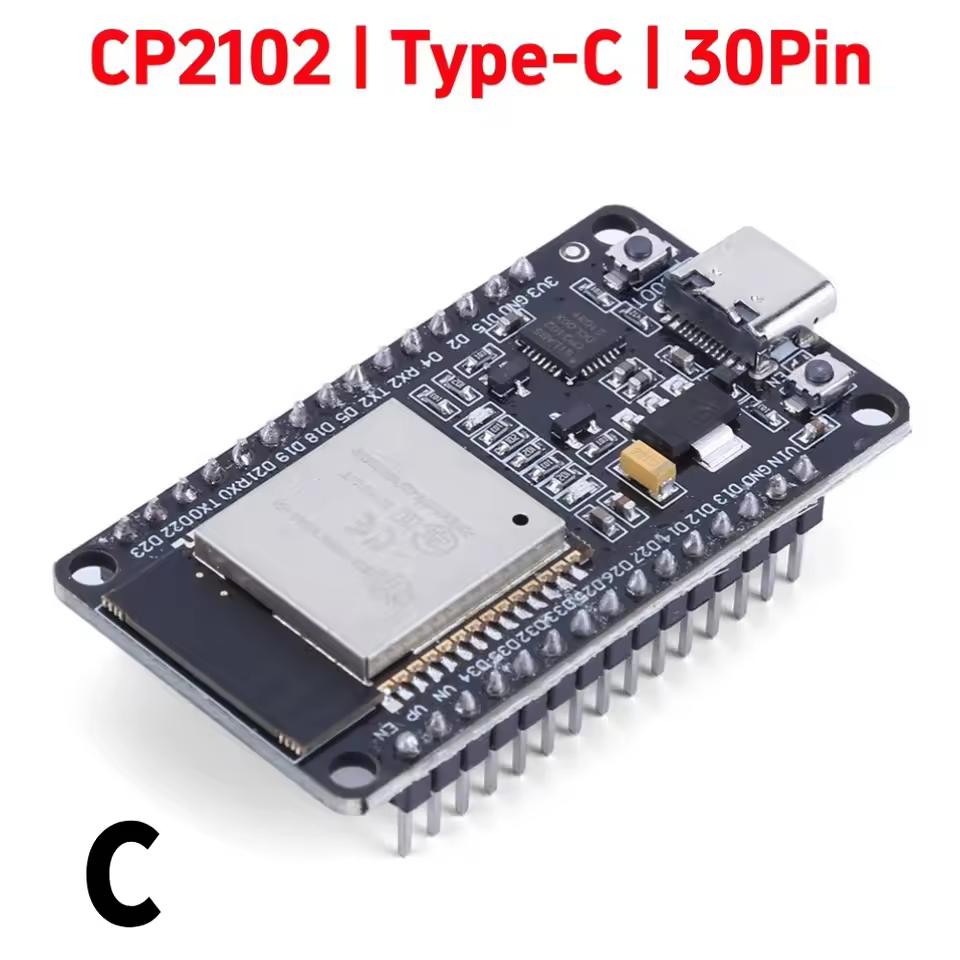 |
ESP32 | CP2102 NodeMCU-32S | https://fr.aliexpress.com/item/1005009683698872.html | 4,59€ |
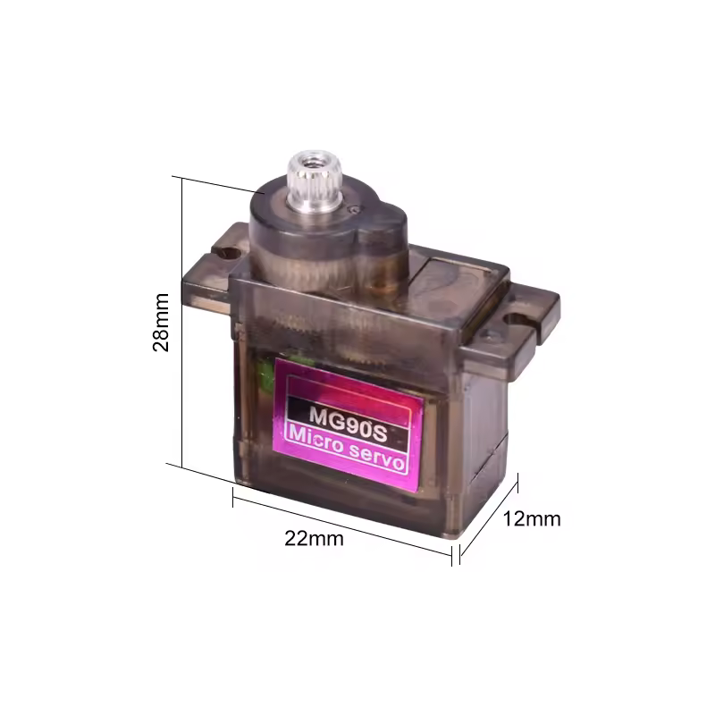 |
Servo Motors | MG90S Metal Gear Digital 9g Servo | https://fr.aliexpress.com/item/4001193413905.html | 4,89€ (4 pcs) |
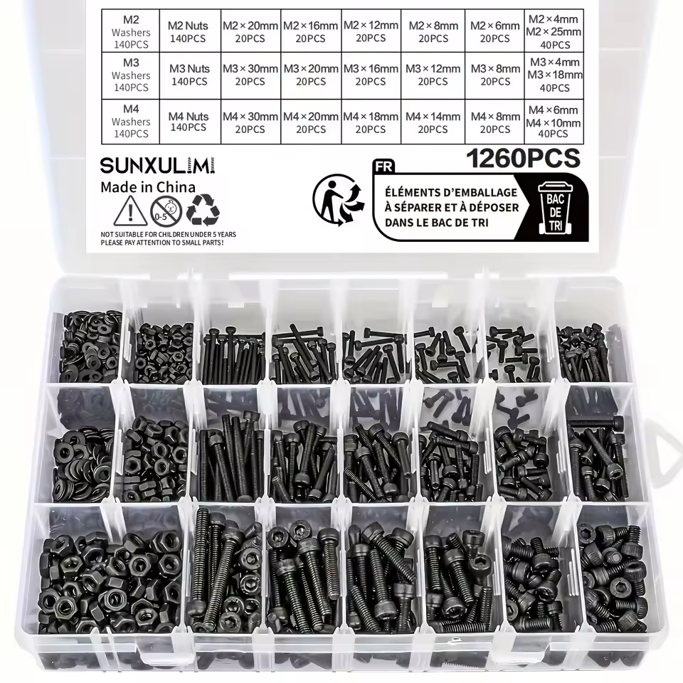 |
Bolts and Nuts | 1260pcs Metric Bolt Assortment - M2 M3 M4, 21 Sizes 4MM To 30MM 12.9 Alloy Steel Bolts And Nuts Kit | https://fr.aliexpress.com/item/1005009858588611.html | 17.19€ |
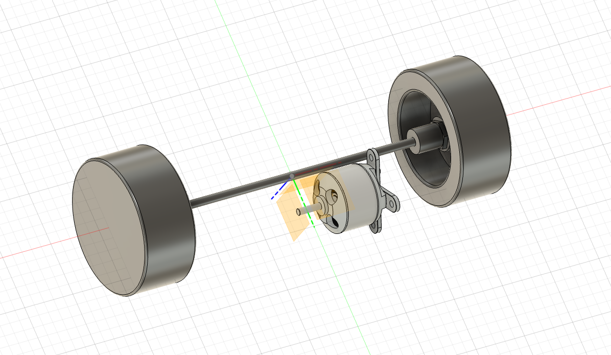
03 - Start Modeling using fusion 360
These parts are more than enough to begin modeling the RC car, starting with the rear drivetrain. Since importing real-world objects into Fusion 360 isn’t currently possible, each hardware component must be modeled manually or sourced from existing 3D models online. In many cases, detailed specifications—including dimensions—are available, which makes it possible to start modeling even before the components arrive. For more complex elements, such as the brushless motor, I was able to find a ready-made 3D model, which saved significant time in the initial design phase.
04 - Gear Modeling by a N00b
Gears turned out to be more complex than I expected. Once I started researching, I realized they can even influence the overall size of the drivetrain. Let’s break it down:
Motor rpm (Revolution per minute)
In my case KV = 2200 rpm/v, if used with a 3S li-ion at 11.1v, it gives 24,420 rpm
Wheel circumference
In my case = 3.14 * 65mm = 204.2 mm
Wheel rpm
Gear ratio x:x (motor/wheel or commonly used spur_teeth/pinion_teeth)
- When ratio > 1 => reduction (more torque at wheel, lower top speed).
- Ratio < 1=overdrive (wheel faster than motor — not common with small pinion < spur setups).
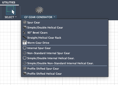
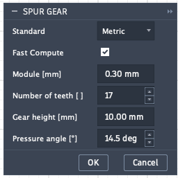
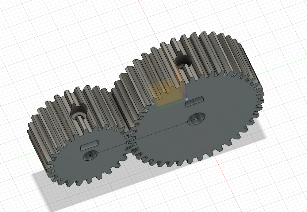
On fusion 360, there is a Free add-in in Autodesk called GF Gear Generator. You just fill in the parameters and Voilà! Here's the parameter I've used:
- Module: 0.8
- Pressure Angle: 14.5 deg
- Motor teeth: 25
- Shaft teeth: 40
⚠️ I am a complete noob in gear dimensioning, My gear ratio should be around 1.6, but I might be completly off, I am learning by doing and testing.
In real gear design, it’s not enough for the teeth to mesh correctly—the gear also needs a reliable way to attach to the shaft. This usually requires a mechanical fastening system such as a screw tightened onto a flat side of the shaft, or an embedded brass insert or captive nut inside the gear body. These features prevent slipping under load and ensure the gear rotates firmly with the shaft, especially when dealing with high-speed brushless motors.
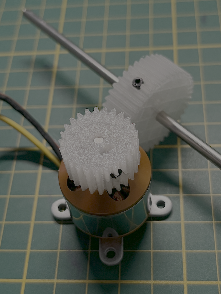
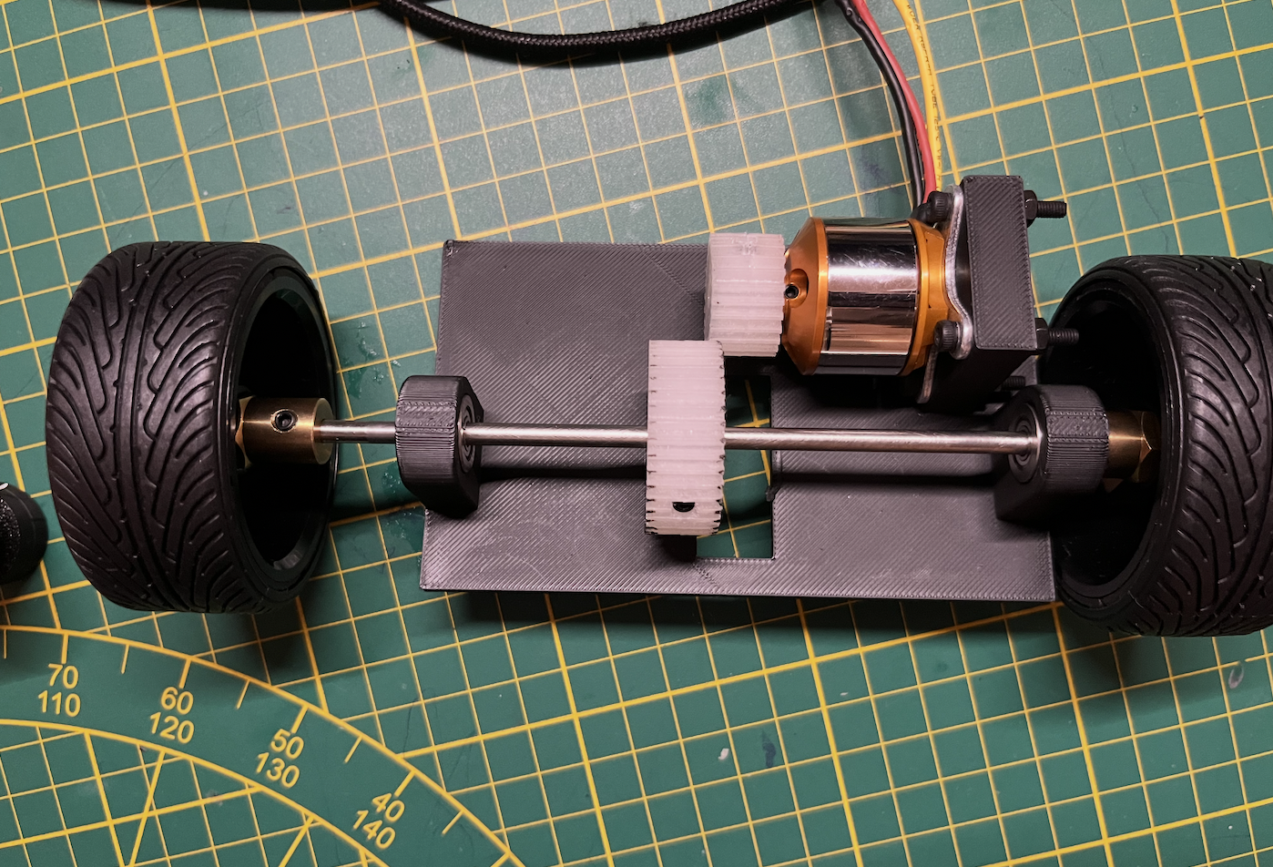
05 - Test fit (and found my first issue)
After lightly sanding the axle with sandpaper while it was spinning in a drill, everything fit perfectly. The gears meshed smoothly with the right amount of clearance, and the wheels rotated freely. However, I realized I had overlooked something during the modeling stage: the rear axle could slide left and right 🤦. I came up with two possible solutions:
- The complex option: redesign everything using double-helical gears, which naturally prevent lateral movement. But that would mean redoing the gear models, and I’m concerned about introducing stress points on the teeth where the screw attaches.
- The easy option: add two small 3D-printed clips on the axle, each with a small indentation so they only press against the rotating part of the bearing.
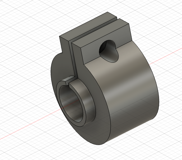
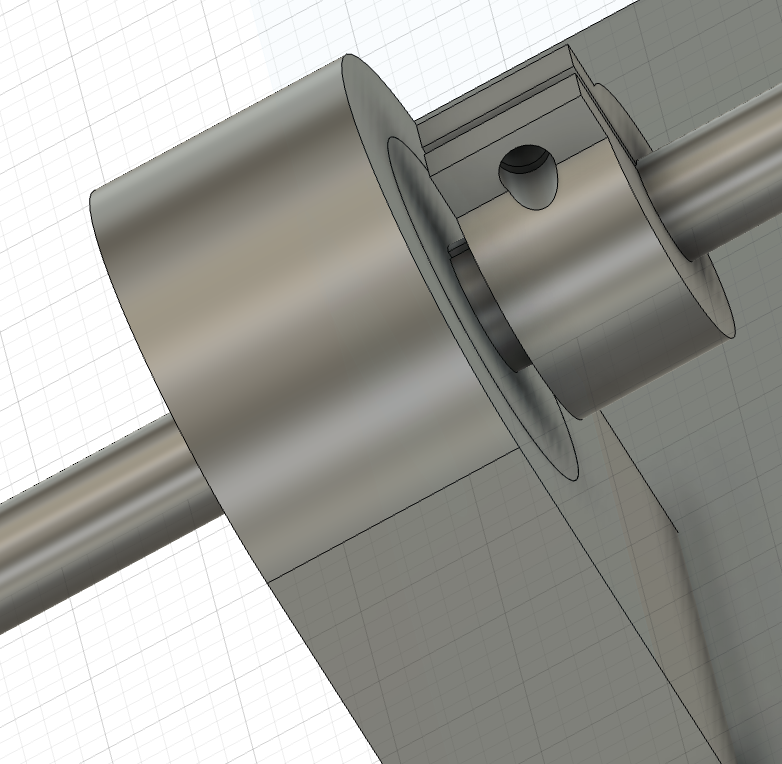
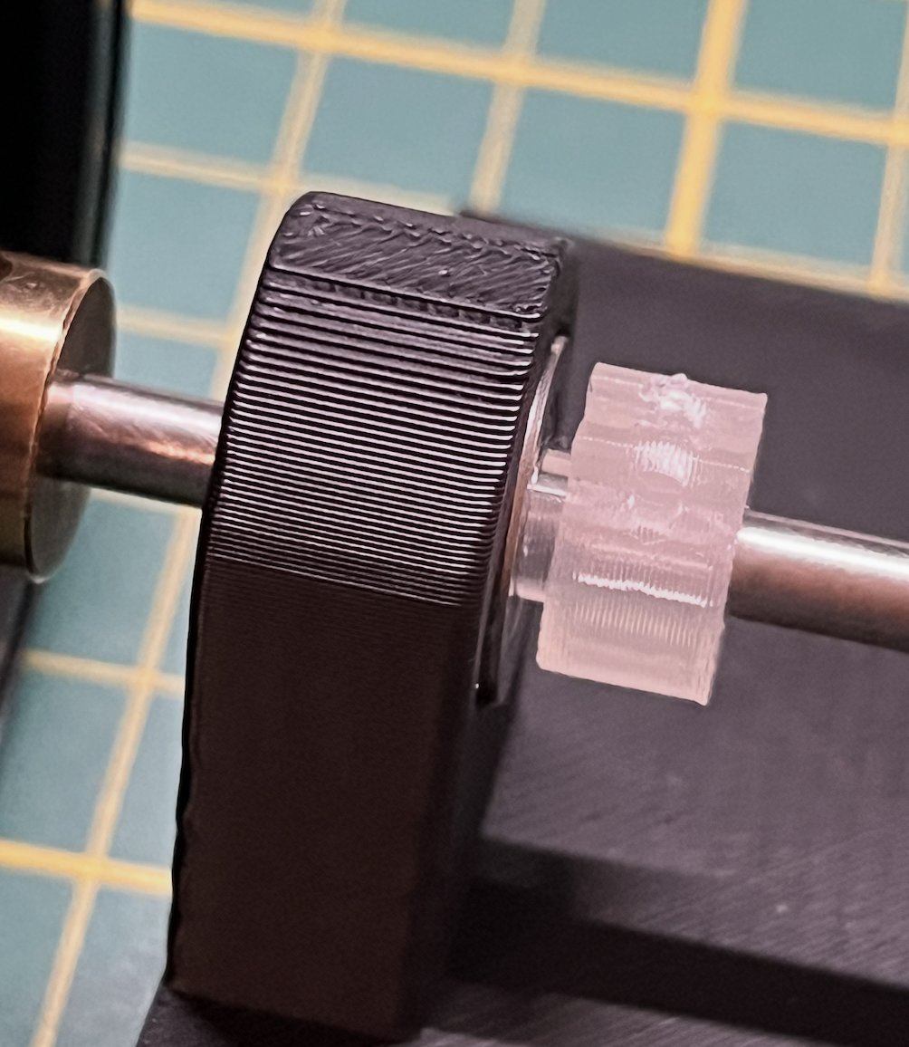
The clip
I've designed it so I screw in a bolt but it seemed to be tight enought like this. I'll see how it goes without, I can always add it later
06 - Hitting the Brakes: Lessons in Torque
Sometimes the best part of a DIY journey is knowing when to pivot. After my first real-world test, I realized my gear ratio and motor setup had a classic "all show, no go" problem: the wheels spun like lightning in the air, but the second they touched the carpet, the car wouldn't budge. As a newcomer to small-scale mechanics, I’ve realized this build is a bit more ambitious than I initially anticipated. I’m suspending work on the RC car for now to focus on projects that are a better fit for my current skill set. I'll be back for a rematch once I’ve brushed up on my mechanical engineering!