3D-Printed, Spring-Loaded, Parametric, Magnetic Solder Holder
So Many Fancy Words for Such a Small DIY
I used to be so bad at soldering… now I’m just bad 😅. I’ve come to believe that being good at soldering is about 50% practice and 50% having the right equipment. Last year I bought a proper soldering station with a heat gun, and it’s been doing a solid job so far.
But even with better gear, you quickly realize that having a few “helping hands” is absolutely essential if you want your solder joints to look even remotely respectable. I did came accros magnetic helping hands (there is a lot of different modals online). But I decided to build my own, because why not ?
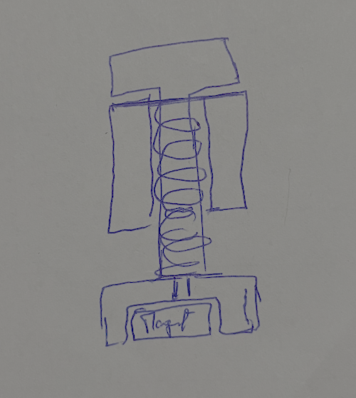
Step 1: Do a rough sketch
Designing a part is one thing — but designing multiple pieces that actually fit together later is a whole different level of brain gymnastics. Here's what I've came up with:
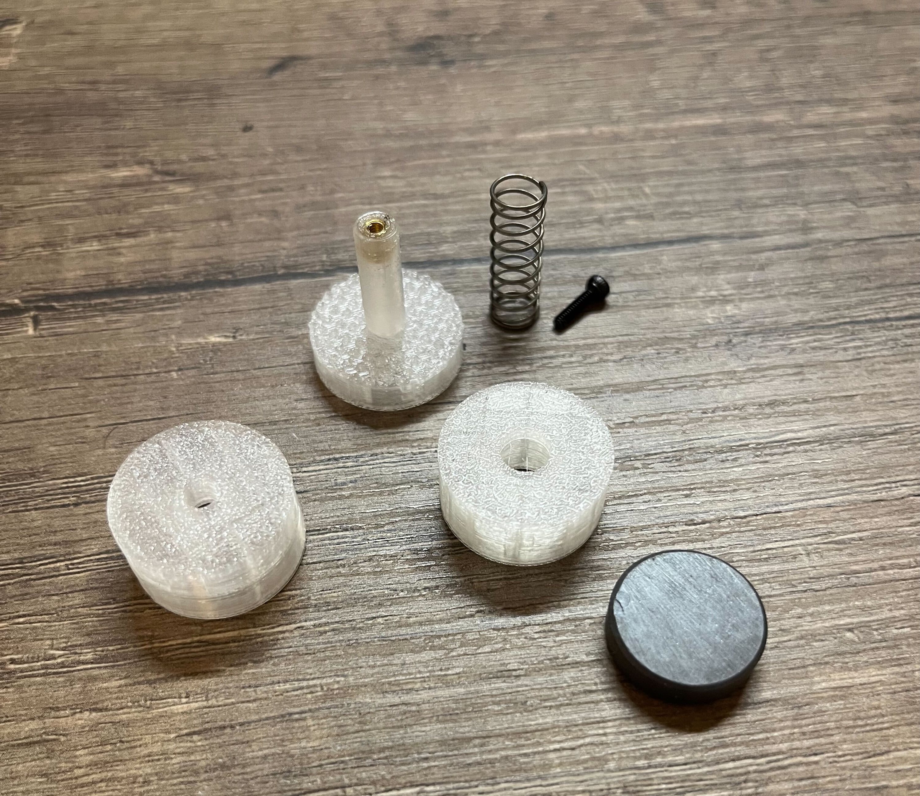
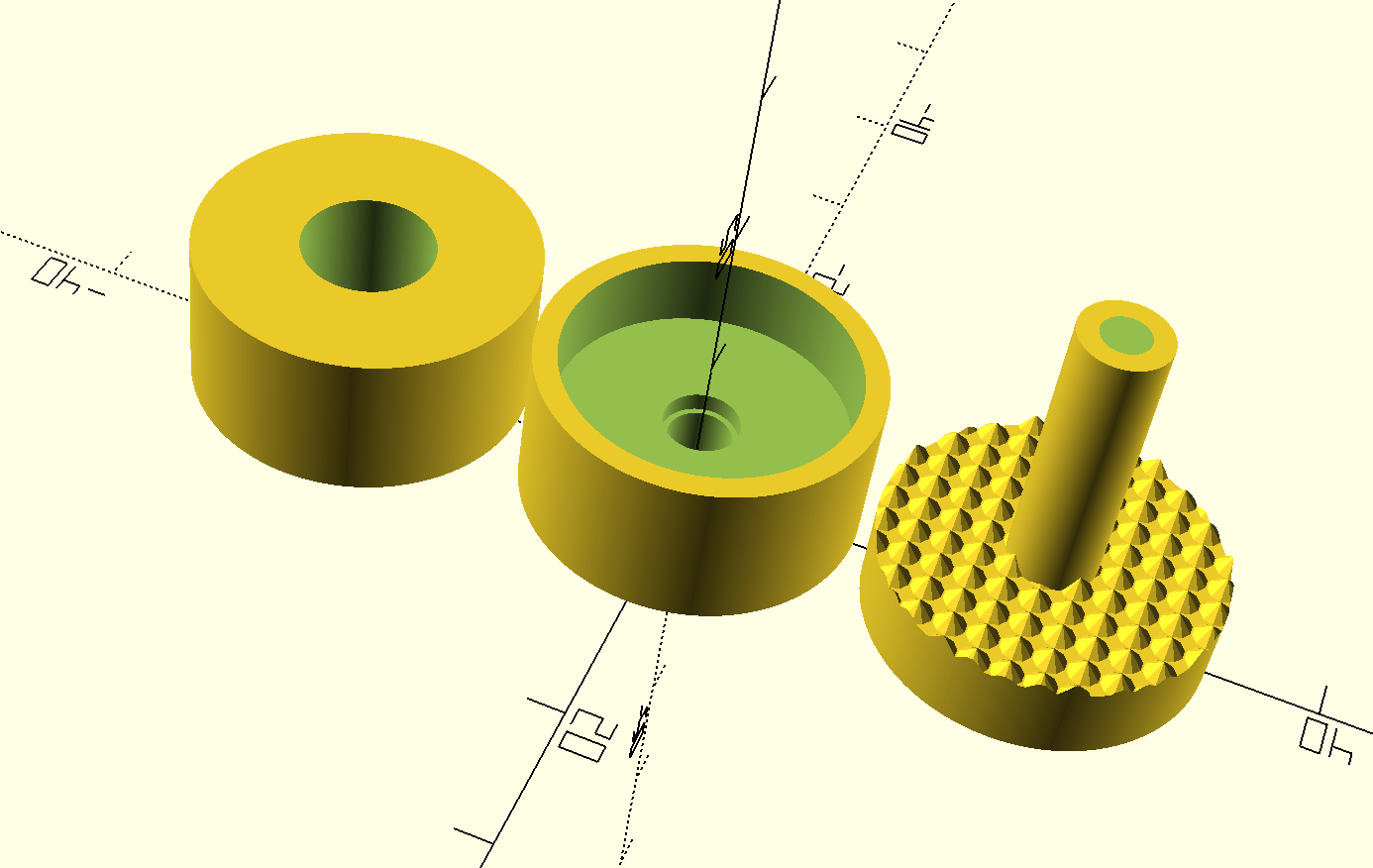
- The Magnet Holder (the base): This is the chunky bottom part that keeps everything stable. It holds a magnet press-fit inside. It also includes a cavity for a screw
- The Slipper (the guide tube): This piece sits above the base and acts as a guide for the plunger. It has a hollow core where the spring sits, and just enough clearance so the plunger can slide smoothly.
- The Plunger (the spring-loaded pusher): This is the moving part that sits inside the slipper, pushed upward by the spring.
You also need a screw, threaded insert, a magnet and a metalic base plate.
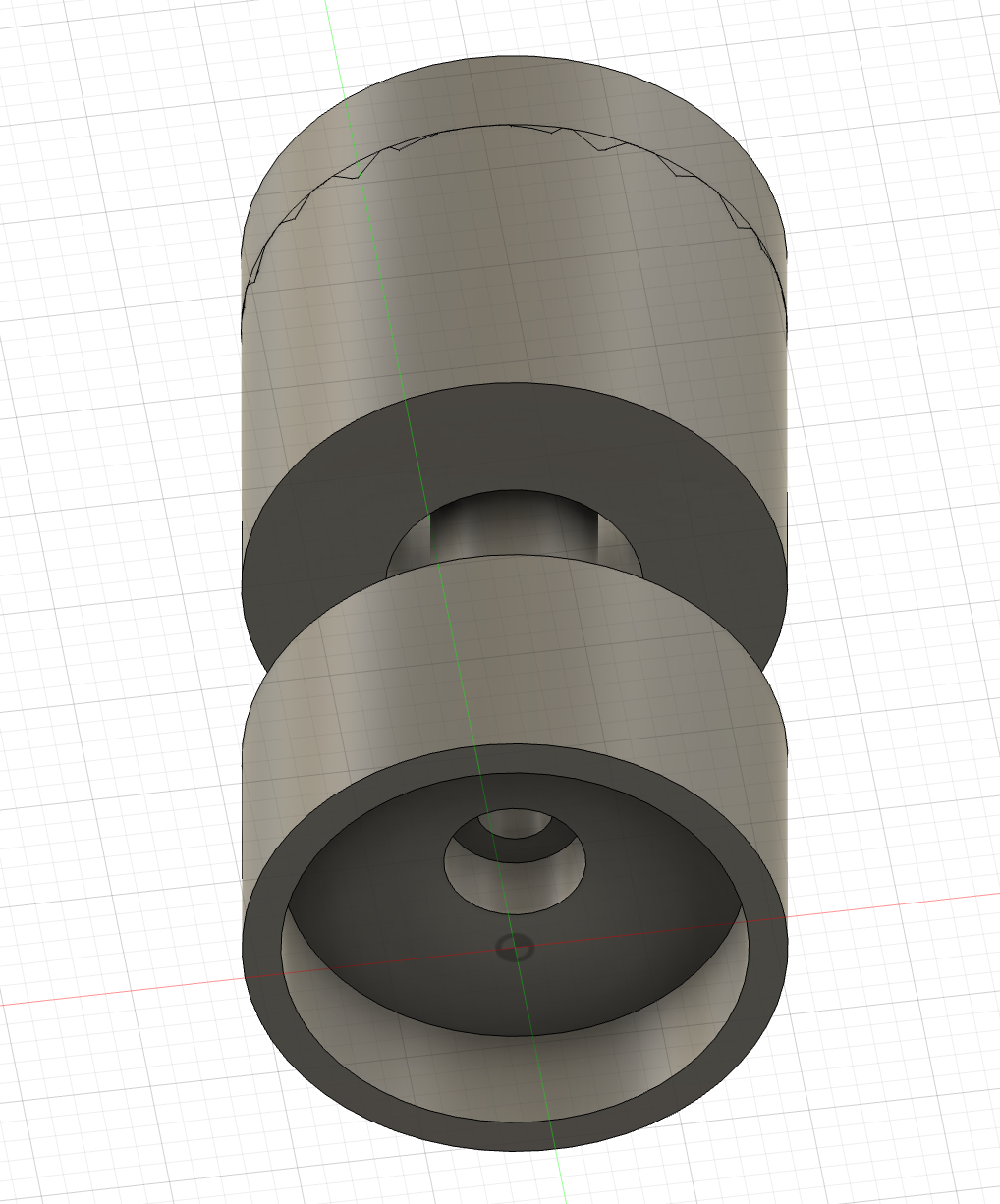
Step 2: Model on Fusion 360
To create a functional and printable 3D design, it’s important to account for tolerances and clearances, as well as how the individual parts will be assembled. Components that appear to fit perfectly in CAD may bind, collide, or fuse together once printed due to factors like material expansion, extrusion width, or printer calibration. Proper tolerances ensure that sliding parts move smoothly, cylindrical parts rotate or align correctly, and press-fit components can be inserted without excessive force.
Step 3: Model on OpenScad to make it parametric
Since I may need several of these holders—and because the springs, magnets, and screw sizes I have on hand all vary slightly from one piece to another—I decided to build the design parametrically in OpenSCAD. By defining all the critical dimensions as parameters, the model can automatically adjust to different component sizes. This approach allows me to generate new STL files quickly and reliably, without having to redesign the entire model each time the hardware changes.
$fn = 360;

// ============================================================
// Magnet & Holder Parameters
// ============================================================
magnet_diameter        = 18.1;
magnet_height          = 5;
magnet_tolerance       = 0.2;

holder_wall_thickness  = 3;
screw_head_height      = 2;
screw_head_diameter    = 3.75;
screw_shaft_length     = 9.8;
screw_shaft_diameter   = 3;
screw_tolerance        = 1;

// Derived dimensions
holder_total_height =
    magnet_height
  + screw_head_height
  + holder_wall_thickness
  + magnet_tolerance;

holder_outer_radius =
    (magnet_diameter / 2)
  + (magnet_tolerance / 2)
  + (holder_wall_thickness / 2);


// ============================================================
// Spring & Plunger Parameters
// ============================================================
spring_free_height     = 21;
spring_outer_diameter  = 7.3;
spring_inner_diameter  = 6.6;
spring_tolerance       = 1;

plunger_base_height    = 5;
plunger_slide_height   = (spring_free_height * 0.75);
plunger_diameter       = spring_inner_diameter - spring_tolerance;

// ============================================================
// Slipper (Plunger Guide) Parameters
// ============================================================
slipper_wall_thickness = 2;
slipper_inner_clearance = 0.4;
slipper_height         = 10;

// ============================================================
// Threaded Insert
// ============================================================
insert_diameter        = 3;


// ============================================================
// MAGNET HOLDER
// ============================================================
difference() {
    // Outer shell
    cylinder(h = holder_total_height, r = holder_outer_radius);

    // Magnet cavity
    translate([0, 0, holder_total_height - magnet_height + magnet_tolerance])
        cylinder(h = magnet_height + magnet_tolerance,
                 r = magnet_diameter/2 + magnet_tolerance/2);

    // Screw shaft clearance
    cylinder(h = holder_total_height,
             r = screw_shaft_diameter/2 + screw_tolerance/2);

    // Screw head clearance
    translate([0, 0, holder_wall_thickness + magnet_tolerance + screw_tolerance])
        cylinder(h = screw_head_height,
                 r = screw_head_diameter/2 + screw_tolerance/2);
}


// ============================================================
// SLIPPER (SPRING GUIDE)
// ============================================================
translate([0, -2*holder_outer_radius-1, 0]) {
    difference() {
        // Outer body
        cylinder(h = slipper_height, r = holder_outer_radius);

        // Plunger sliding channel
        cylinder(h = slipper_height,
                 r = plunger_diameter/2 + slipper_inner_clearance);

        // Spring cavity
        translate([0, 0, slipper_wall_thickness])
            cylinder(h = slipper_height - slipper_wall_thickness,
                     r = spring_outer_diameter/2 + spring_tolerance/2);
    }
}


// ============================================================
// PLUNGER BODY
// ============================================================
plunger_total_height = plunger_slide_height + slipper_wall_thickness;

translate([0, 2*holder_outer_radius+1, 0]) {
    union() {
        // Base platform
        cylinder(h = plunger_base_height, r = holder_outer_radius);

        // Sliding plunger shaft
        translate([0, 0, plunger_base_height])
            difference() {
                cylinder(h = plunger_total_height,
                         r = plunger_diameter/2);

                // Threaded insert cavity (vertical)
                translate([0, 0, plunger_total_height])
                    cylinder(h = screw_shaft_length,
                             r = insert_diameter/2);
            }
    }
}


// ============================================================
// PLUNGER GRIP SURFACE (TEXTURED TOP)
// ============================================================
count = round(holder_outer_radius/2);
translate([0, 2*holder_outer_radius+1, plunger_base_height]) {
    difference() {

        // Texture bumps
        for (x = [-count : count])
            for (y = [-count : count])
                translate([2*x, 2*y, 0])
                    cylinder(h = 1, r1 = 1, r2 = 0, $fn = 10);

        // Outer ring holding the texture
        difference() {
            cylinder(h = plunger_base_height,
                     r = 2 * holder_outer_radius);

            cylinder(h = plunger_base_height,
                     r = holder_outer_radius);
        }
    }
}
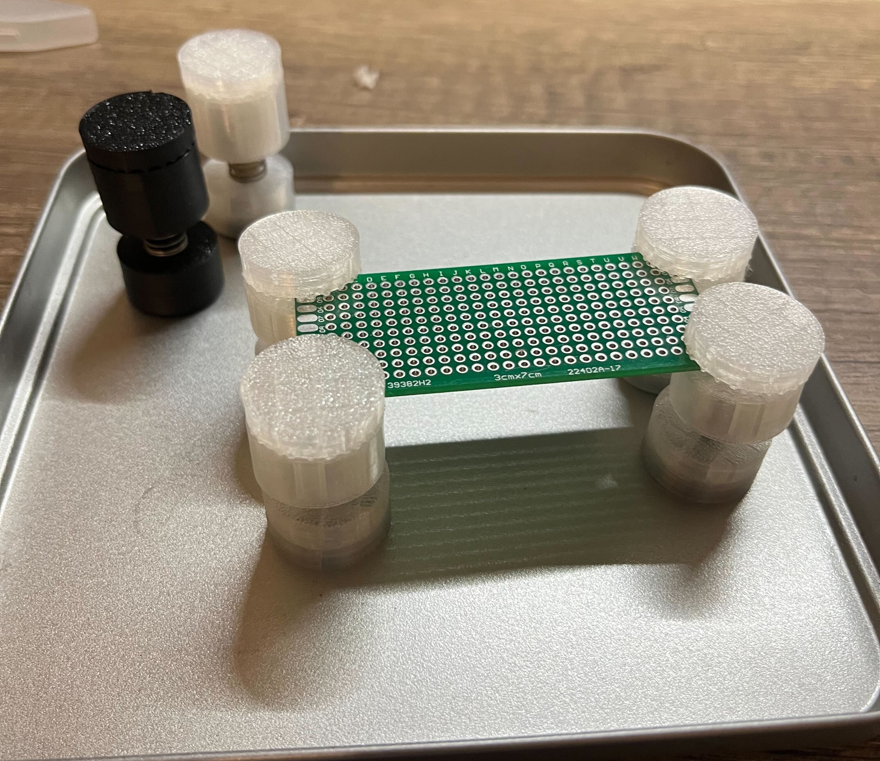
Step 4: Mount everything and enjoy
Print a couple of them, in various sizes and heights and voilà !